HA IPSec VPN with BGP Dynamic Routing between two pfSense Appliances

In this post I will setup an IPSec dynamic route-based vpn tunnel between two pfSense Appliances.
The Architecture
 ------ WAN1 -----
 |               |
PF1 -- WAN2 -- PF2
 |               |
LAN             LAN

WAN1: 192.168.0.0/24       (Bridge)
WAN2: 192.168.0/24         (Host Only)
PF1 - LAN: 192.168.57.0/24 (Host Only)
PF2 - LAN: 192.168.58.0/24 (Host Only)
pfsense1:
WAN1: 192.168.0.52
WAN2: 192.168.56.52
LAN:  192.168.57.52
IPSEC-VTI-IP1: 10.10.10.1
IPSEC-VTI-IP2: 10.10.10.5

pfsense2:
WAN1: 192.168.0.53  /24
WAN2: 192.168.56.53 /24
LAN:  192.168.58.53 /24
IPSEC-VTI-IP1: 10.10.10.2
IPSEC-VTI-IP2: 10.10.10.6
Firewall rules For IPSEC
https://docs.netgate.com/pfsense/en/latest/book/ipsec/ipsec-and-firewall-rules.html
When an IPsec tunnel is configured, pfSense® automatically adds hidden firewall rules to allow UDP ports 500 and 4500, and the ESP protocol from the Remote gateway IP address destined to the Interface IP address specified in the tunnel configuration.
UDP Port 4500 is only required for NAT Traversal if the pfSense Applicance doesn’t have a public IP and is behind a NAT device.
IPSEC S2S VPN
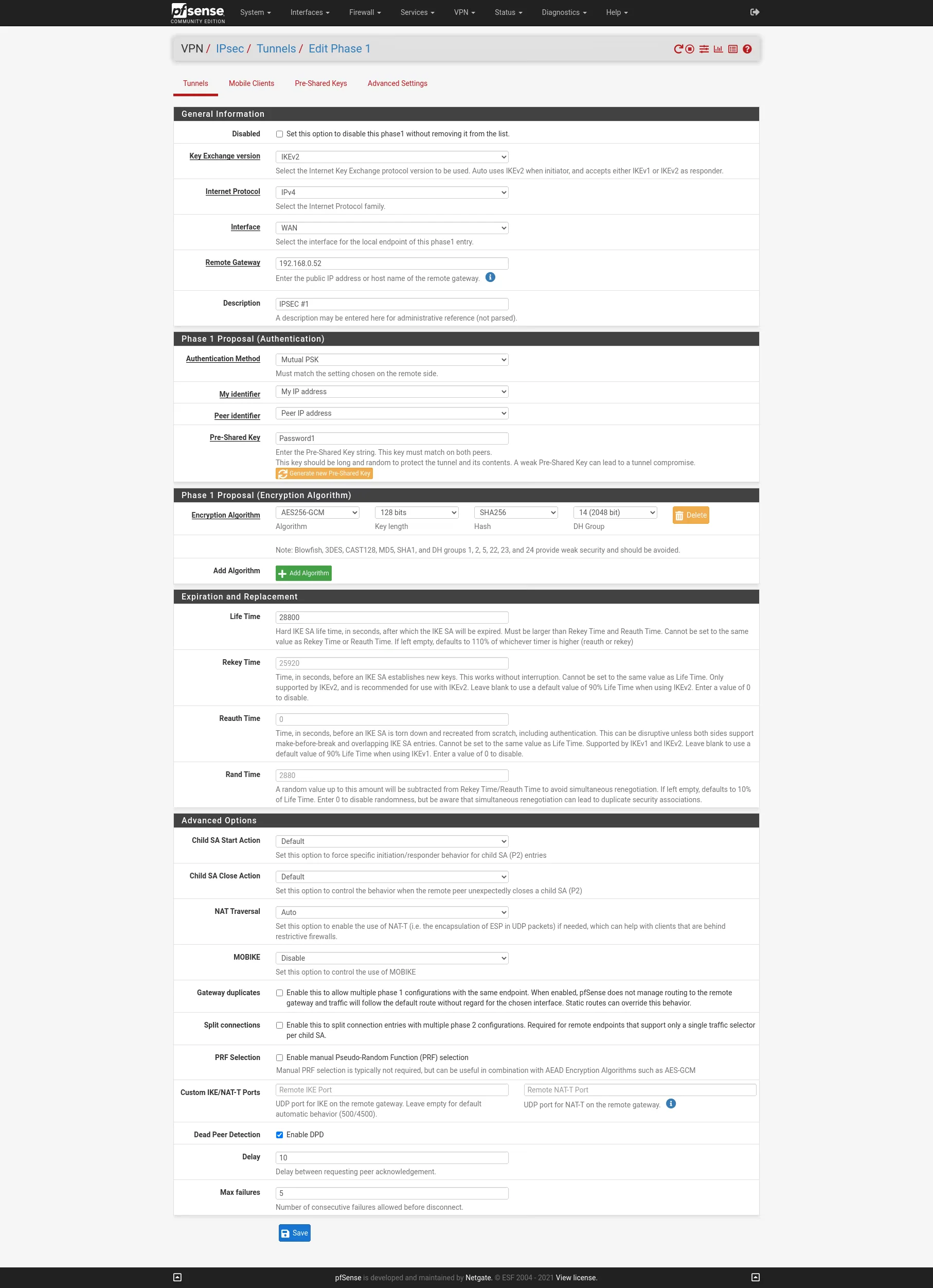
On the two WAN interfaces of the firewalls I will create two IPSEC S2S VPN with Routed IPsec (VTI). First we must configure on each site the PSec Phase 1 for boat the VPNs.
Site A


Site B

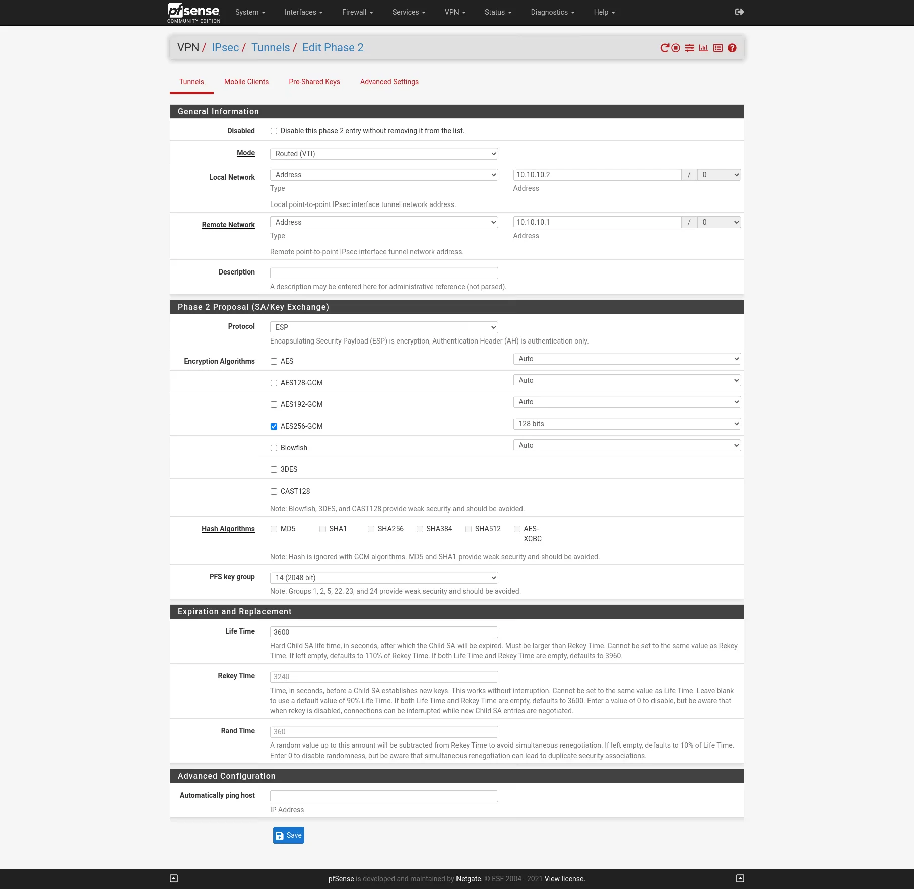
Now after we finished configure the Phase 1 on each site we add an IPSec Phase 2 on each site. I will use Mode Routed (VTI). In this mode we must create a transit network with a subnet mask of /30.
Site A


Site B

Create Virtual inteface for the Routed (VTI)
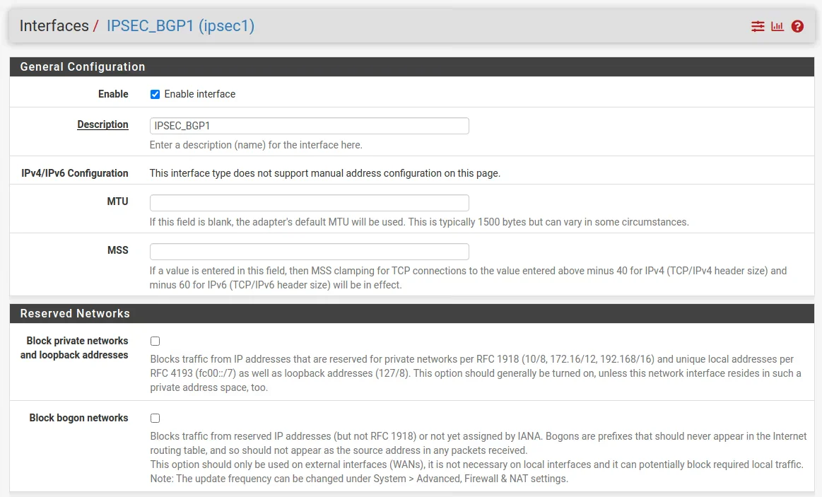
Go to Interfaces -> Assignement Assign and enable the new ipsec interfaces:
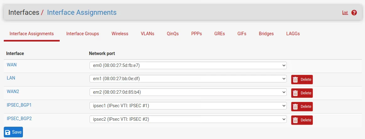
Enable Interface but do not configure the ip. It will be automatically assigned by th VPN.
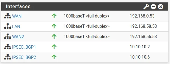
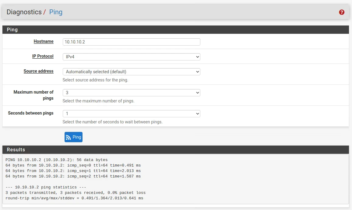
As you cans see the ip is automaticle assined to the interfaces:
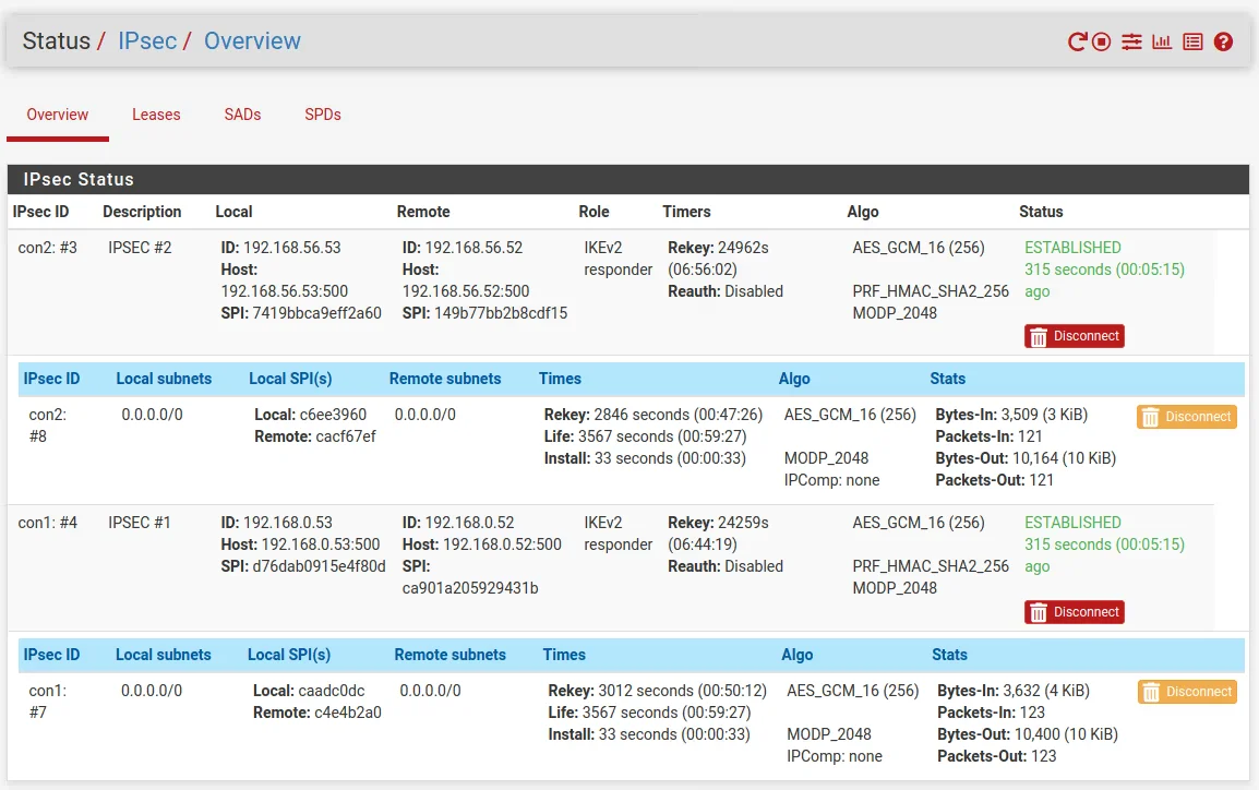
To see if the tunnel is up and running go to Status -> IPSec in the menu. As you can see the connection between both peers is established.
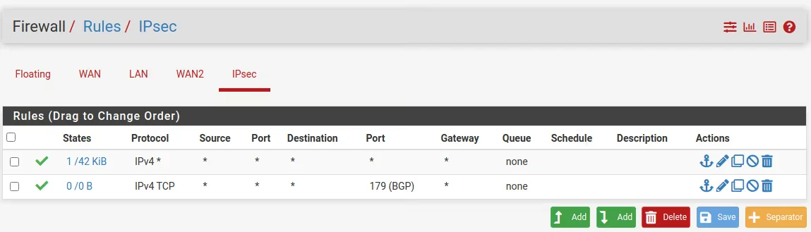
Add firewall rules for the IPSEC
One last thing we must configure on each site that traffic can flow from the remote site to the local site are the IPSec Firewall Rules .
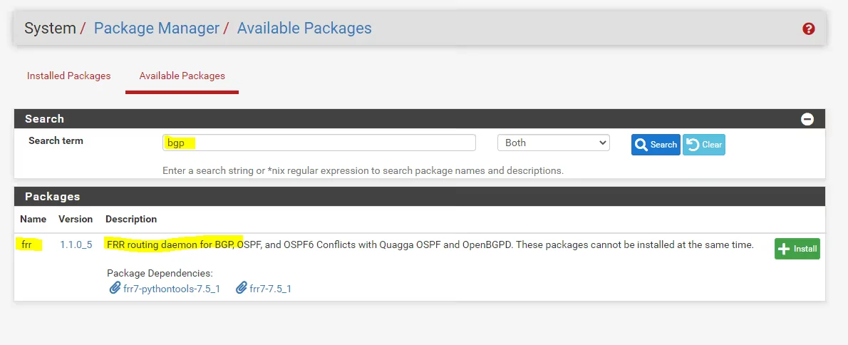
Install the FRR Package
Go to System -> Package Manager -> Available Packages and search for bgp or frr to find and install the package.
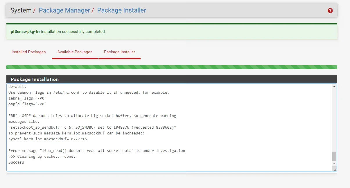
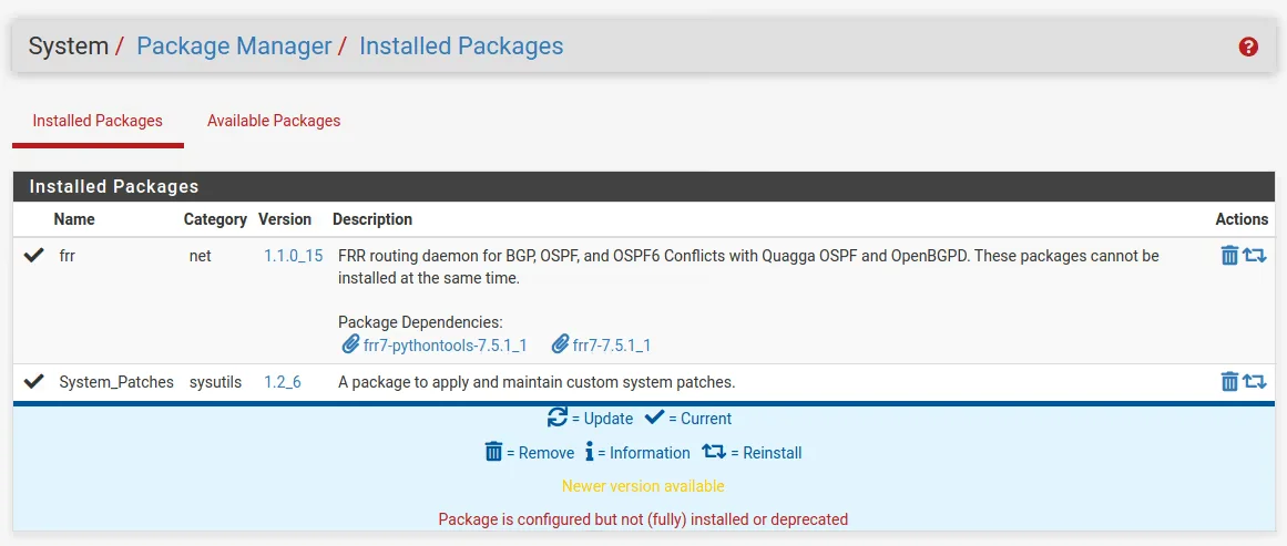
Install the package on tha master and the slave server too. The packagas dose not syncronise between cluster members.
Configure dynamic routing
But before traffic will be routed over the tunnel we first must configure the BGP Protocol on both sites at pfSense.
zebra is an IP routing manager. It provides kernel routing table updates, interface lookups, and redistribution of routes between different routing protocols.
Packages do not synchronize with XMLRPC unless they implement their own XMLRPC synchronization settings, and FRR does not do that currently. You will have to set it up on both nodes separately for the time being.
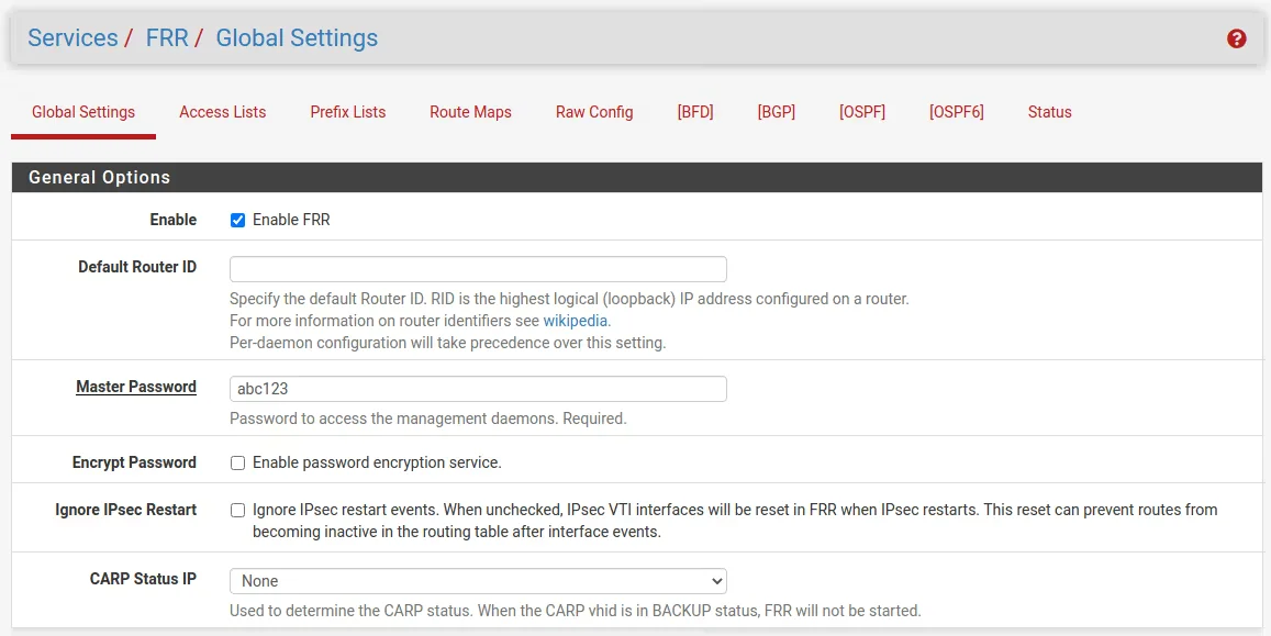
First we click and go to the Services -> FRR Global/Zebra configuration.
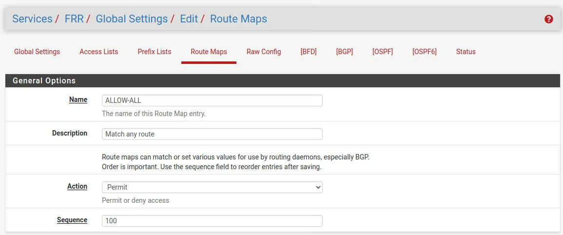
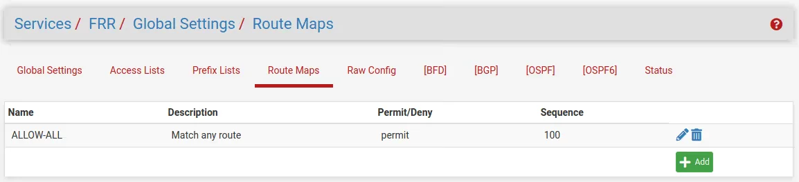
Before configuring BGP, add a route map to match any routes so it can be used by FRR to allow exchanging all routes with the peer. Navigate to Services > FRR Global/Zebra, Route Maps tab
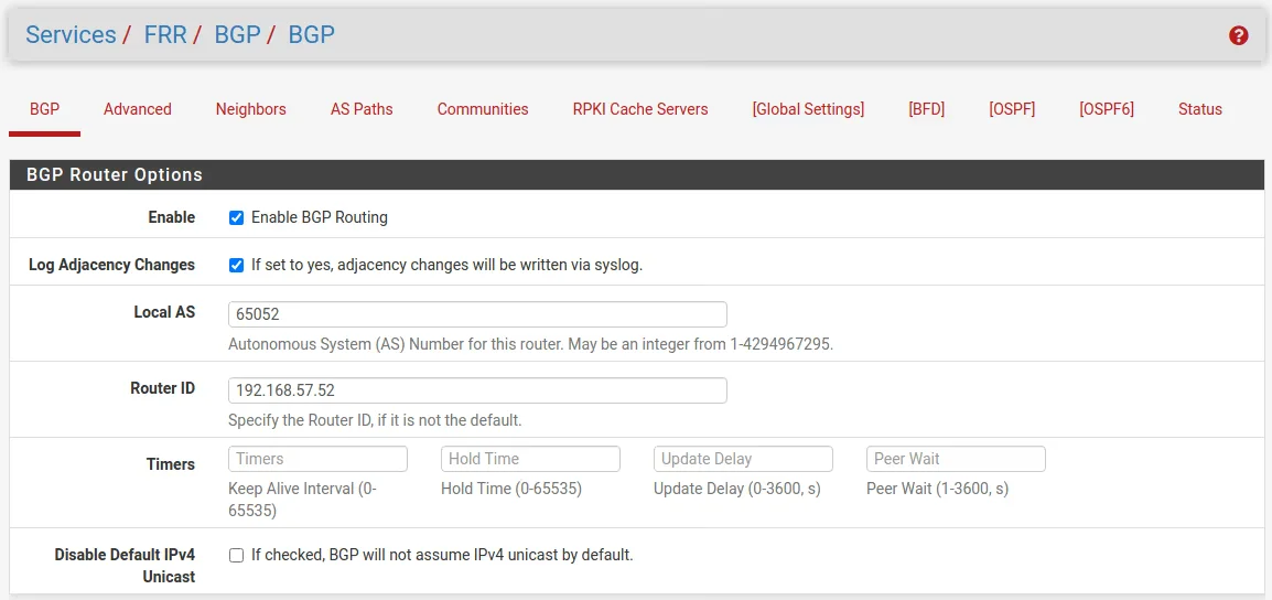
Configure BGP
Now we can switch to the BGP configuration, therefore you can click in the Global Settings sections menu on BGP with the square brackets or from the main menu under Services -> FRR BGP. Here you must configure the BGP Protocol for each site. As Router IP you must enter the internal IP from the LAN interface.
https://en.wikipedia.org/wiki/Autonomous_system_(Internet)
(64512 – 65534 Reserved for private use RFC1930, RFC6996)
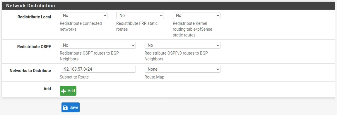
Site A
Also we need to configure here in the Network Distribution section which networks we want to advertise to the other BGP peer.
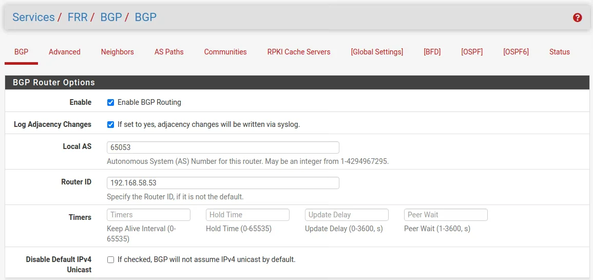
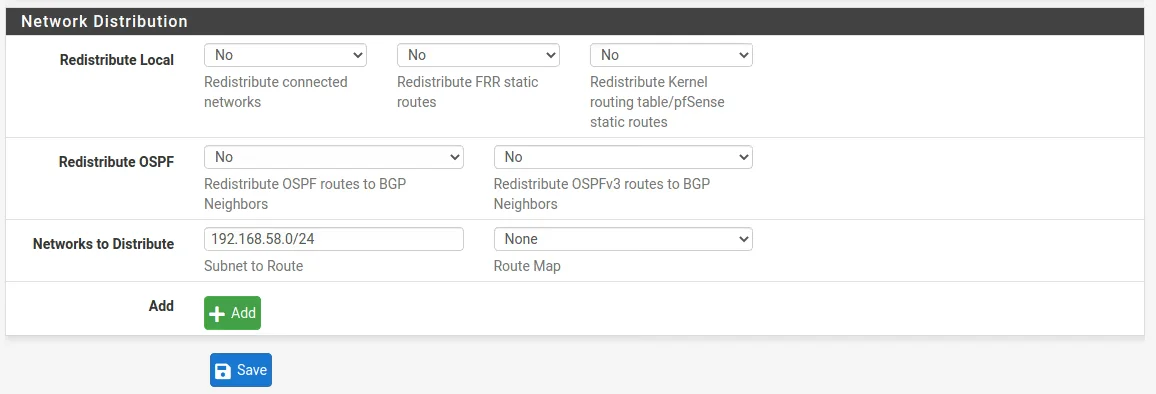
Site B
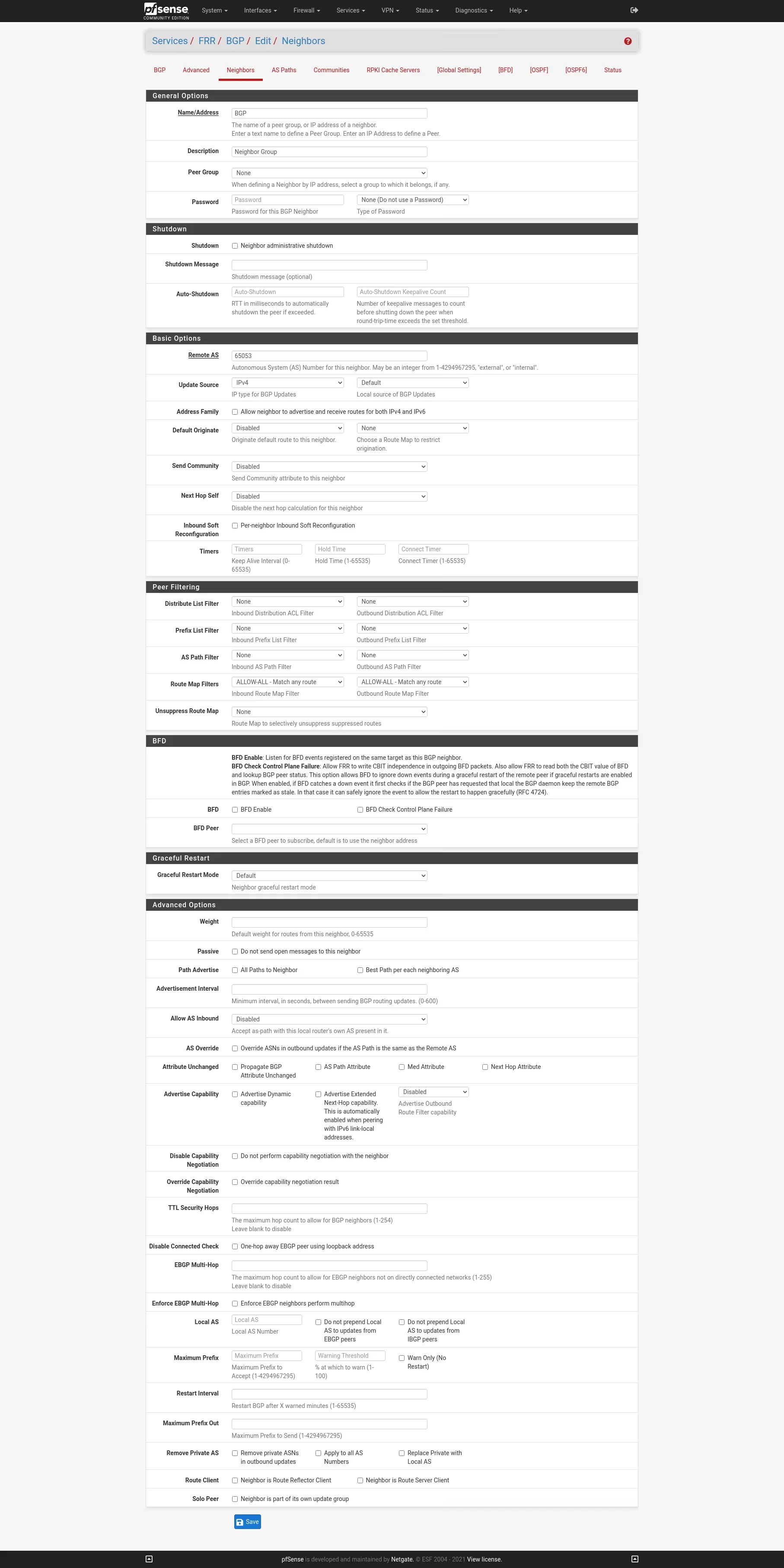
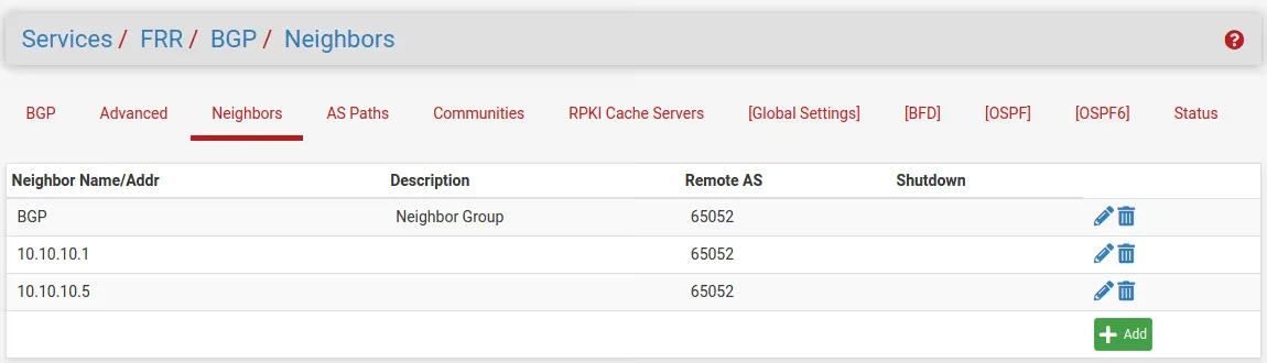
Configure Neighbors
Now we move on to the Neighbors menu where first I create a Neighbor callef BGP. When you add a name instead of the ip of the Neighbor the frr will interpreter this as a Peer Group. At the Route Map Filters eet both Inbound and Outbound to ALLOW-ALL.
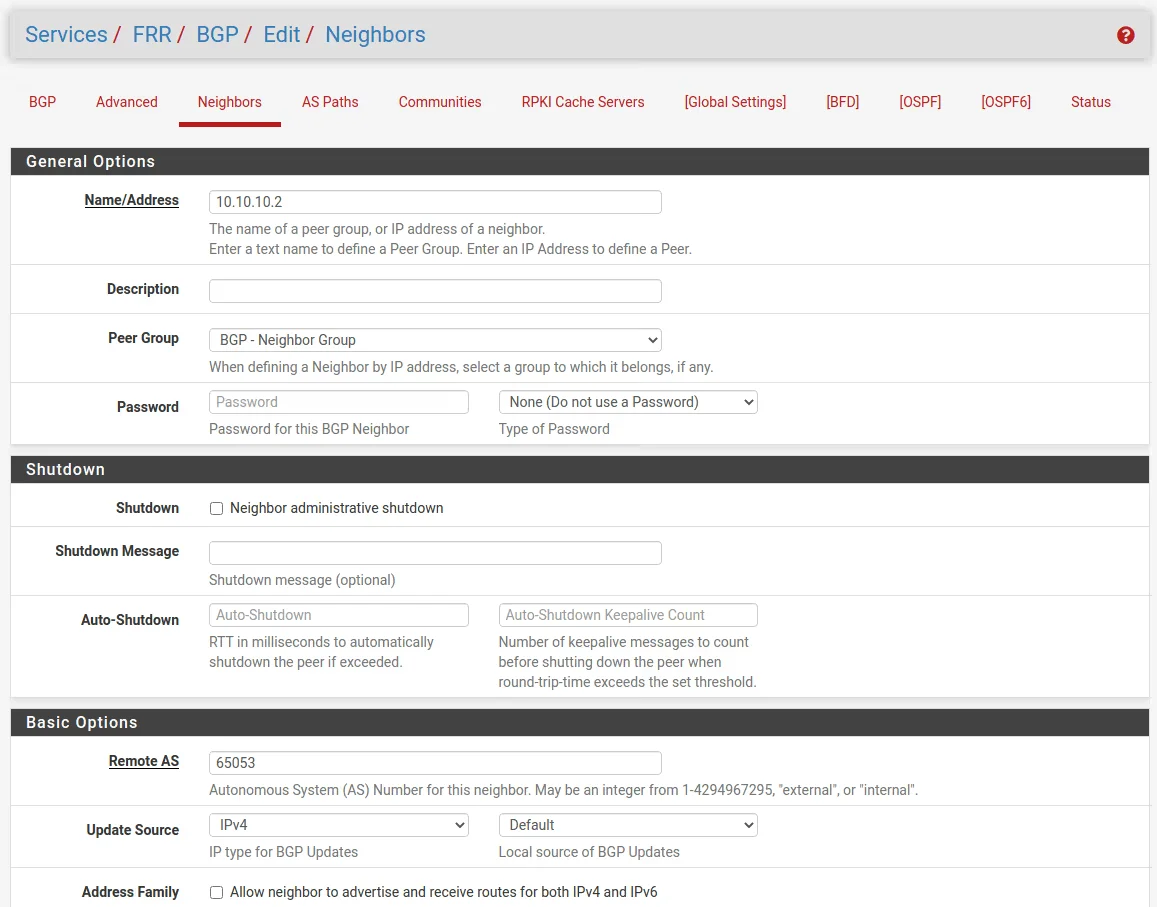
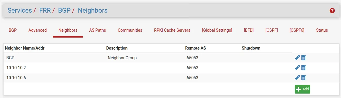
Then create the Neighbors and use the Peer Group BGP.
Site A
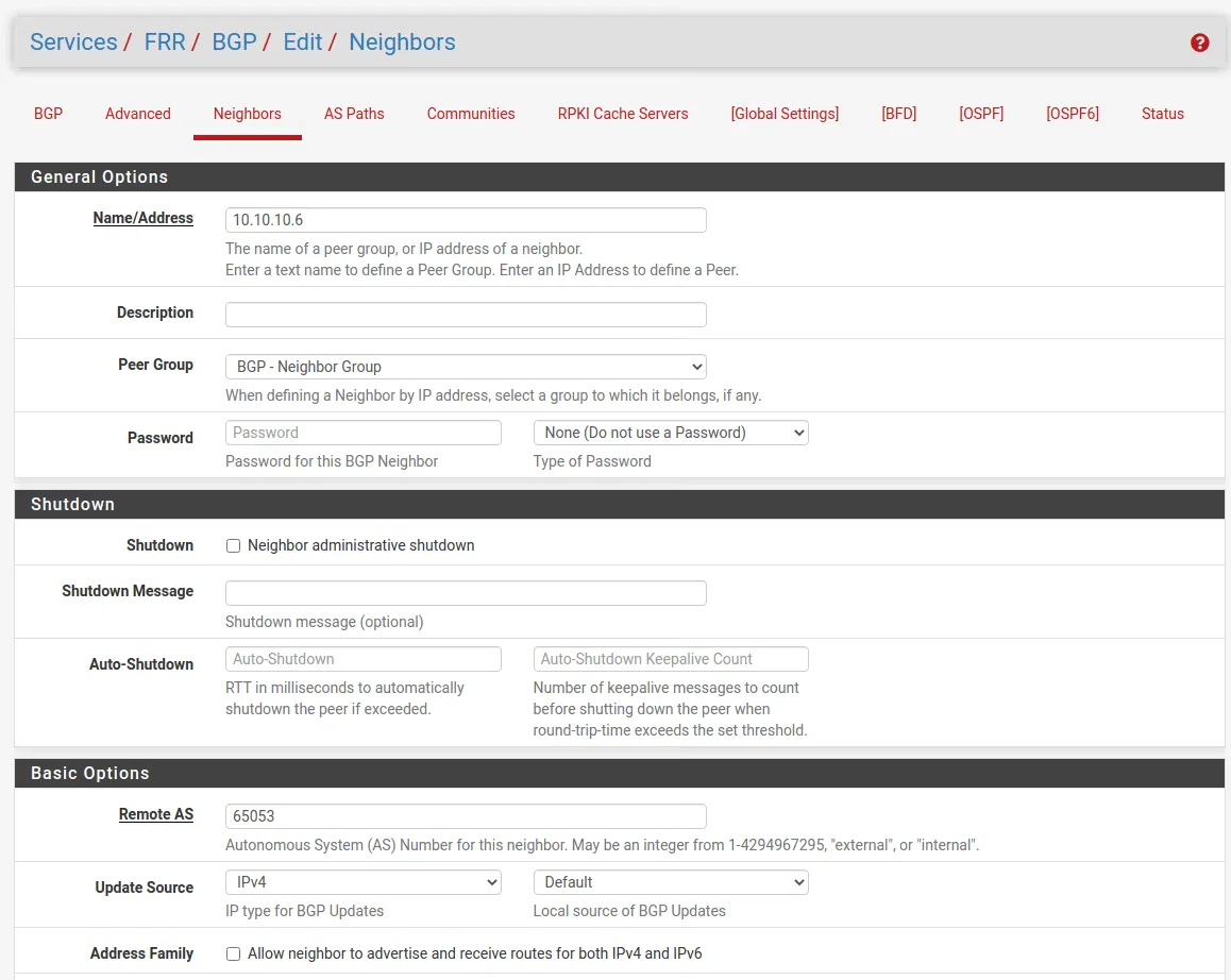
Site B
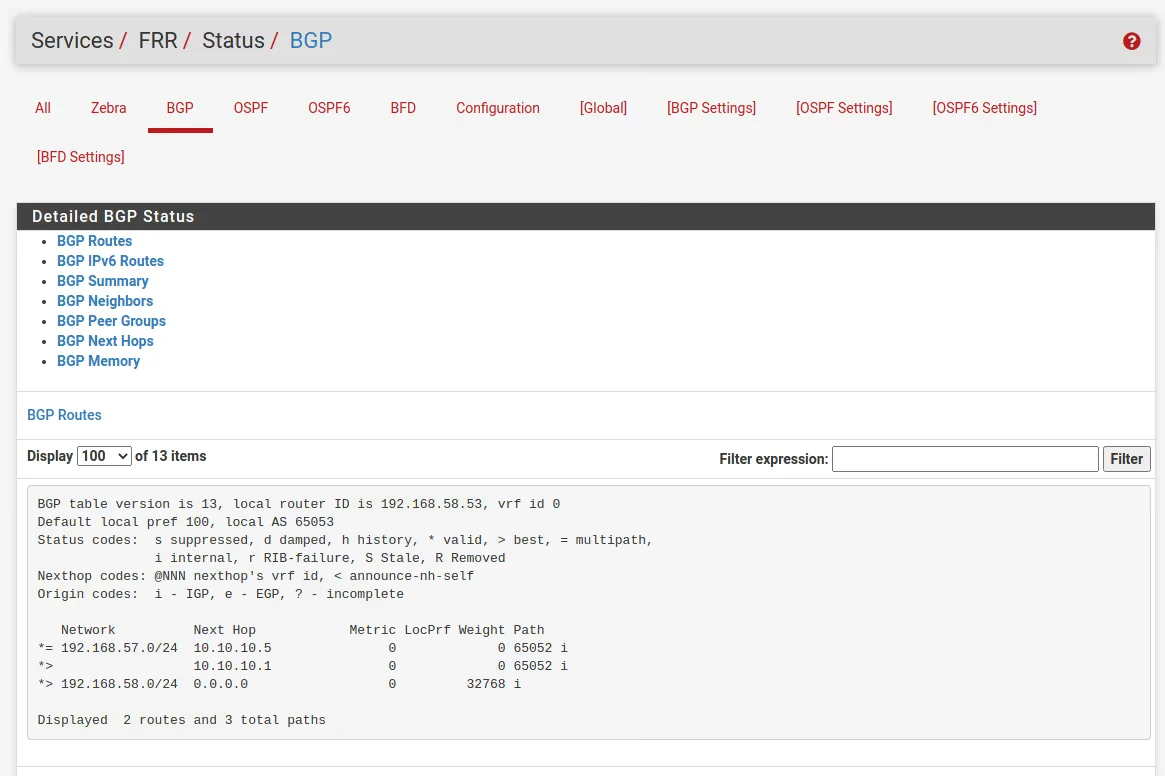
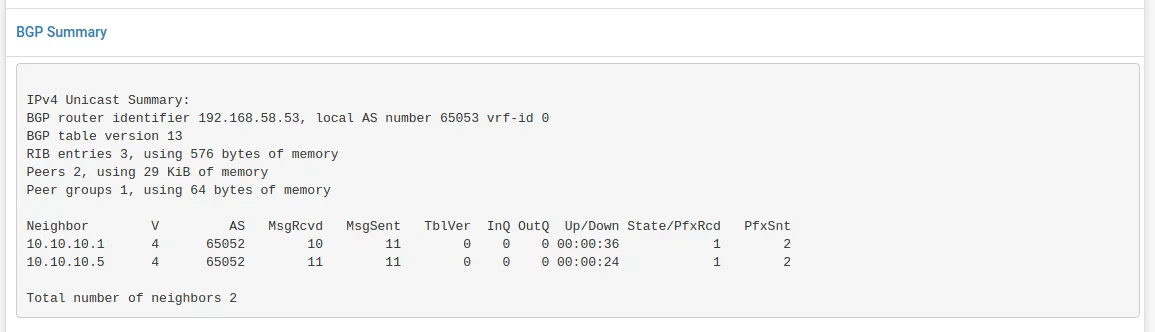
Check The BGP STatus
The result for these settings you will see under Services -> FRR -> Status -> BGP in the BGP table.
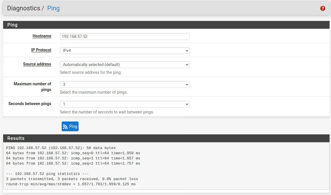
Test the results
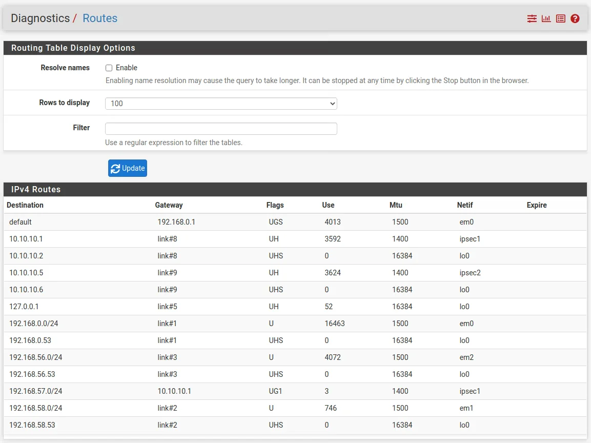
Further we can see this advertised route from the other peer, under Diagnostics -> Routes